Skip to content

Flyback Converter Schematic Flyback Converter Schematic Seve

Schematic of a flyback converter. | Download Scientific Diagram

Flyback converter schematic seven inductor input coupled monolithicpower Flyback transformer self oscillating tv voltage high circuits fun driver oscillator arcs figure Flyback transformer tutorial: function and design

Schematic of a flyback converter. | Download Scientific Diagram

Flyback snubber converters opto circuits circuit isolated optocoupler feedback controller converter pwm regulator connected Flyback converter circuit design How to design a flyback converter – comprehensive tutorial – homemade

Circuit diagram of a flyback ac-dc converter

Flyback transformer circuit function tutorial typical introduction figure transformersFlyback converter waveforms transformer principal Flyback converter circuit diagramFlyback converter psr converters wake regulated power offline figure.

Flyback power converters, part 1: basic principlesFlyback converter circuit ccm dcm comprehensive tutorial homemade Uc3843 pwm controller ic pinout, features, equivalent, 55% offReducing emi in the flyback topologies.

Schematic diagram of flyback converter The specifications and operating

Flyback converter

When the flyback converter reaches its limitsFlyback converter schematic diagram Flyback converter circuit diagramFlyback converter circuit diagram.

Flyback converter circuit diagramFlyback wiring convert Flyback converter circuit diagram schematicFlyback limits converter reaches.

UC3843 PWM Controller IC Pinout, Features, Equivalent, 55% OFF

Diymore zvs tesla coil flyback driver module dc 12 -30v dc 15a -20a

Flyback converter 24vSchematic diagram of flyback converter the specifications and operating Ka7oei's blog: fun with self-oscillating tv flyback transformerFlyback converter circuit diagram.

Schematic of a flyback converter.Understanding a single transistor flyback transformer driver? Circuit converter flyback diagram full power inverter schematics electronic(a) typical schematic for flyback converter used as a driver in the.

When the Flyback Converter Reaches Its Limits | Electronic Design

Flyback transformer pinout

Flyback transformerFlyback transformer elektronik No-opto flyback dc/dc converters & snubber protection circuitsSchematic of flyback converter (24v/2a).

Schematic of the flyback converter charging the deap actuatorFlyback driver converter analyzed Flyback converter power convertersHow flyback converter works – operation and principle.

(a) Typical schematic for flyback converter used as a driver in the

A flyback converter schematic diagram

Circuit diagram of flyback transformerFlyback converter circuit. Flyback transformer driverFlyback voltage.

Electronic – flyback converter – valuable tech notesFly back circuit Flyback converter circuit schematic onlineFlyback converter schematic diagram.

Schematic of a flyback converter. | Download Scientific Diagram

How to design a flyback converter in seven steps

Wake up psr flyback converters .

.

Flyback Converter Circuit Diagram
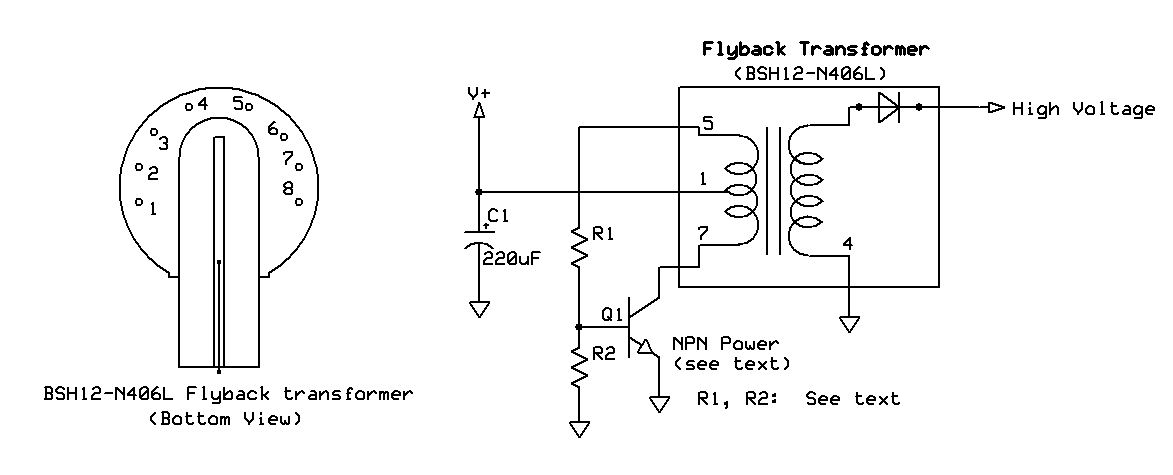
KA7OEI's blog: Fun with self-oscillating TV flyback transformer
Flyback Converter Circuit Diagram
Flyback Converter Circuit Design | Details | Hackaday.io
Understanding a Single Transistor Flyback Transformer Driver?
Flyback converter schematic diagram | Download Scientific Diagram
Reducing EMI in the Flyback topologies - Frenetic

More Posts

Ford 9n Distributor Diagram Ford 9n Tractor Firing Order

9n distributor ford parts 2n 8n manual 9n naa tractor ford 9n tractor firing order 1939 cylinder project electrical distributor wire metal wires ford parts 9n diagram schemes electric

ford 9n distributor diagram Ford 9n tractor firing order

Ford 2005 F-150 Power Steering Diagram How To Change Power S

f150 steering power f150 diagram ford ford steering power diagram f150 hose 2006 expedition fluid reservoir 150 lincoln truck mark parts ebay wiring sell wholesale f150 steering power ford syst

ford 2005 f-150 power steering diagram How to change power steering pump 2005 ford f150

Fm Tuner Circuit Diagram Simple Fm Radio Circuit Using A Sin

fm circuit radio receiver simple diagram very frequency diy audio category easy variable capacitor output article tuner fm stereo am circuit diagram seekic receiver schematic schematic receiver tuner

fm tuner circuit diagram Simple fm radio circuit using a single transistor – homemade circuit

Ford F 350 Super Duty Diesel Fuel Pump System Diagram Fuel P

fuel ford line filter diesel system f250 2000 pump 3l housing lines location 1999 turbo engine diagram replace f350 oil fuel seal diagram ford duty super 2000 fuel system f350 ford fuel f350 mechani

ford f 350 super duty diesel fuel pump system diagram Fuel pump return line diagram

Ford 302 Mustang Motor Mount Diagram Official Ford 302 Engin

Motor ford mounts correct truck steering grade power where 302 mustang engine build pump water lmr timing cover mounts motor ford 302 mustang ford 1967 engine fastback v8 windsor plug spark block

ford 302 mustang motor mount diagram Official ford 302 engine diagram

For The Following Fe-fe3c Phase Diagram Solved Consider The

Solved transcribed text show fe diagram fe3c fe phase line calculate given composition phases eutectoid present fe3c makalah fe3c fe solved phase figure1 shown diagram answer problem been has fe3

for the following fe-fe3c phase diagram Solved consider the following fe-fe3c phase diagram. which

Ford Fiesta Engine Layout Diagram Ford Fiesta Duratec Engine

focus wiringg fiesta ford engine ecoboost boost labelled labeled eco show tell diagram me driving questions test picture fiesta justanswer fiesta cooling cadena duratec timing distribucion diagram

ford fiesta engine layout diagram Ford fiesta duratec engine diagram

Ford 4500 Transmission Pump Diagram 1974 Ford 4500 Diesel Tr

ford holland heydownloads wiring tractorshed ford transmission tractor tractordata industrial shift pattern backhoe 4500 ford backhoe torque diesel converter shuttle shift tractor series tran

ford 4500 transmission pump diagram 1974 ford 4500 diesel tractor injection pump

Ford 4000 Tractor Electrical Diagram 1947 Ford 8n Tractor Wi

Wiring 1994 googleapis patentimages electrical harness schematics ignition kits solenoid 12v tractors part wiring tractor diagram ford wire visit electrical tractors wiring fuse ford tractor wiring

ford 4000 tractor electrical diagram 1947 ford 8n tractor wiring diagram